

Intelligent frequency meter
- cpfl:
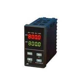
203 series of intelligent frequency meter/tachometer is suitable for speed, line speed and frequency…
Description
203 series of intelligent frequency meter/tachometer is suitable for speed, line speed and frequency measurement. Microprocessor is used for control operation. The intelligent frequency meter/tachometer can freely convert the input frequency to a wide range of scales (such as speed, linear speed, etc.). Low functional features multiple protection, isolation design, strong anti-jamming capability, high reliability, good software platform, the secondary development ability, in order to meet the special functional requirements with the calibration, calibration and perfect the function of the sensor fixed network communication function, and all kinds of belt two-way communication serial input/output equipment, main technical index of network control system is low basic error: 0.5% FS or 0.2% FS + 1 word display way: double row four digital tube LED display or single row six LED digital tube display sampling period: 0.2 S input signals: Analog 1-5v or 4-20ma two-line pulse, TTL pulse, NPN, PNP voltage pulse measurement range: 0.1 ~ 9999HZ
Alarm output: second limit or fourth limit, alarm mode and alarm sensitivity can be set, relay output contact capacity AC220V/3A or AC220V/1A. Communication output: interface mode -- isolated serial two-way communication interface RS485/RS422/RS232/Modem baud rate --300 ~ 9600bps internal setting transmission output: 4 ~ 20mA, 0 ~ 10mA, 1 ~ 5V, 0 ~ 5V precision: ± 0.3% FS feed output: DC24V/30mA power source: switching power supply 85 ~ 265VAC power consumption 4W
Type spectrum | Said Ming | ||||||||
203 | Intelligent frequency meter, tachometer, line speed meter | ||||||||
Installation dimensions | a. | Horizontal 160×80×125 mm (double row and four LED display) | |||||||
A/L | Horizontal 160×80×125 mm (single row six LED display) | ||||||||
A/S | Vertical 80 x 160 x 125 mm | ||||||||
B | Methods 96 x 96 x 110 mm | ||||||||
C | Horizontal type 96 x 48 x 110 mm | ||||||||
C/S | Vertical 48 * 96 * 110 mm | ||||||||
D | Methods 72 x 72 x 110 mm | ||||||||
F | Methods 48 x 48 x 110 mm | ||||||||
Alarm points | B - | B0 has no output; B1 - B4, 1-4 PM | |||||||
Analog output | The X1 | 4-20 ma output | |||||||
X2 | 0 to 10 ma output | ||||||||
The X3 | 1-5 v output | ||||||||
X4 | 0 to 5 v output | ||||||||
- to lose out | P | microprinter | |||||||
R | Serial communication RS232 | ||||||||
s. | Serial communication RS485 | ||||||||
Power supply for transmitter | 220 vac power supply | ||||||||
V12 | Output with DC12V feed | ||||||||
V24 | Output with DC24V feed | ||||||||
For electric power source | Switch quantity | ||||||||
220 vac power supply | |||||||||
W. | DC24V power supply | ||||||||
Lose the signal | M1 | NPN pulse | |||||||
M2 | PNP pulse | ||||||||
The M3 | TTL pulses | ||||||||
The M4 | Analog 1 ~ 5V or 4 ~ 20mA pulse | ||||||||
The M5 | MV signal (applicable to magnetoelectric proximity switch) | ||||||||
Model example: 203CB2X1V24M3 203 series intelligent frequency meter/tachometer, TTL pulse signal input, external size 96×48×110mm, 2 relays control output, with 4 ~ 20mA transformer output, with DC24V feed output, power supply 220VAC.
Browse:
