

Glass rotameter
- cpfl:
LZB/LZJ glass rotor flowmeters are widely used in chemical, petroleum, light industry, medicine, env…
Description
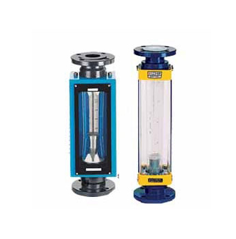
LZB/LZJ glass rotor flowmeters are widely used in chemical, petroleum, light industry, medicine, environmental protection, food and measurement testing, scientific research and other departments to measure the flow of single-phase non-pulsating fluid (liquid or gas). Glass rotameter has strong corrosion resistance, can detect acid (except hydrogen acid), alkali, oxidizer and other corrosive gas or liquid flow, suitable for chemical, pharmaceutical, paper, sewage treatment and other industries.
Principle and structure
The glass rotameter is mainly composed of a tapered glass tube that expands from the bottom up and a float that moves up and down with the size of the fluid flow (figure 3). When the fluid passes through the cone tube from bottom to top, the lift force S generated by the kinetic energy of the fluid on the float and the buoyancy force A of the fluid make the float rise. When the sum of the lift force S and buoyancy force A equals G of the float's own gravity, the float is in equilibrium and stable at A certain height. The scale on the cone tube indicates the flow value of the fluid. The float reading position in the flowmeter is shown in figure 2:
The cone tube of the LZB/ lzb-f flowmeter is a smooth inner wall tube (see figure 4). For flowmeters with a diameter of DN15 or above, the float moves up and down through the guide rod to maintain stability. LZJ/LZJ-()F flow meter has three guiding convex bars on the inner wall of the cone tube to keep the float stable (see figure 4). Flowmeters below diameter DN10 are connected with hoses and equipped with needle flow control valves; DN15 flowmeter is connected with flange.
Model specifications and technical parameters
Size DN (m) | Type no. | Measuring range | Spinal canal length (m) | Precision grade | The liquid state is allowed to be measured | |||
20 ℃ water | Air 20℃, 10132SPa | LZB/LZJ | LZB - (F) | Temperature (℃) | Pressure (MPa) | |||
2 | LZB - 2 | From 4 to 0.4 ml/min 0.6 ~ 6 ml/min 1.0 ~ 10 ml/min 1.6 ~ 16 ml/min | 6 to 60 ml/min 10 ~ 16 ~ 160 ml / 100 ml/min min 25 ~ 250 ml/min | 160 | 1.5:2.5 | 2.5:4 | - 20 ~ + 120 | 1 or less |
3 | LZB - 3 | 2.5 ~ 25 ml/min 4 ~ 40 ml/min 6 ~ 60 ml/min 10 ~ 100 ml/min | 40 ~ 60 ~ 400 ml/min 600 ml/min 100 ~ 1000 ml/min 160 ~ 1600 ml/min | |||||
4 | LZB LZB - 4-4 f | (1 ~ 10) L/h (1.6 ~ 16) L/h (2.5 ~ 25 L/h) | (16 ~ 160 L/h) (25 ~ 250 L/h) (40 ~ 400 L/h) | |||||
6 | LZB - 6 LZJ - LZJ - 6 f | (2.5 ~ 25) L/h (4 ~ 40) L/h (6 ~ 60) L/h | (40 ~ 400 L/h) (60 ~ 600 L/h (100 ~ 1000 L/h) | |||||
10 | LZB LZJ - 10-10 LZJ - 10 f | (6 ~ 60) L/h (10 to 100 L/h (16 ~ 160 L/h) | (100 ~ 1000) L/h (160 ~ 1600) L/h (250 ~ 2500) L/h | 2.5 | 0.6 or less | |||
15 | LZB - 15 LZJ - 15 f | (16 ~ 160 L/h) (25 ~ 250 L/h) (40 ~ 400 L/h) | (0.25 ~ 2.5) m after m/h (0.4 ~ 4) after m/h (0.6 ~ 6) after/h | 350 | ||||
25 | LZB - 25 LZJ - 25 f | (40 ~ 400 L/h) (60 ~ 600 L/h (100 ~ 1000 L/h) | After (1 ~ 10) m/h (1.6 ~ 16) m after/h (2.5 ~ 25 m after/h) | |||||
40 | LZB - 40 LZJ - 40 f | (160 ~ 1600) L/h (250 ~ 2500) L/h | (4 ~ 40 m after (6 ~ 60 m/h after/h | 430 | ||||
50 | LZB - 50 LZJ - 50 f | (0.4 ~ 4) m after m/h (0.6 ~ 6) after/h | (10 ~ 100 m) after (16 ~ 160) m/h after/h | 450 | ||||
80 | LZB LZB - 80-80 - f | After (1 ~ 10) m/h (1.6 ~ 16) m after/h | (50 ~ 250 m) after 80 ~ 400) m/h after/h | 500 | 0.4 or less | |||
100 | LZB LZB - 100-100 - f | M (5 ~ 25) after (8 to 40 m/h after/h | (120 ~ 600) m after after/h (200 ~ 1000) m/h | |||||
All stainless steel type
Flange, float, guide rod, support plate and bolt are all 304 stainless steel (1Cr18Ni9Ti), model LZB-()B. If the liquid receiving material is 316, the model is LZB-()Bo, which needs to be customized. For stainless steel lined PTFE, LZB-()BF(or BoF), to order.
The four type
The base, float and needle valves are made of polytetrethylene (PTTFE). Support plate, screws and other stainless steel
Browse:
On A:Metal tube float flowmeter
Next:Turbine flowmeter
